
![]()
Misplacement of V1 and V2
Misplacement of V1 and V2: Don’t let this mistake mess up your ECG interpretation!
The proper location of V1 and V2 have not changed in many decades. They are located in the 4th intercostal space, just right and left, respectively, of the sternum. It is fairly easy to determine this spot using the angle of Louis as a landmark.
However, V1 and V2 were being misplaced pretty much right after being invented. This error in lead positioning usually produces trivial changes in the QRS pattern in those leads, and thus no real change in ECG interpretation. But certain erroneous ECG patterns can be generated, and it is important to recognize lead misplacement as a potential cause.

Recognizing misplacement of V1 and V2
P wave changes
In the vast majority of healthy patients, V1 will have a biphasic P wave, while V2 will be upright. Upwards misplacement should be strongly suspected if the P in V1 is fully negative, or if the P in V2 is biphasic or fully negative. (If the leads are properly placed, consider e.g. atrial enlargement or an ectopic atrial rhythm.)
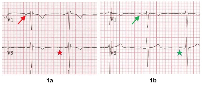
Figure 1a: V1 and V2 are placed too high, the P wave in V1 is fully negative (red arrow), and the P wave in V2 is biphasic (red star).
Figure 1b: The leads are placed at their proper location, V1 shows a mostly-upright biphasic P (green arrow) and a fully upright P in V2 (green star).
Incomplete Right Bundle Branch Block (rSr’pattern)
Upwards misplacement of V1 and V2 often produces an IRBBB pattern.
IRBBB is a normal finding, seen in healthy athletes and children. However, a falsely “new” IRBBB might prompt the unwary clinician to consider pulmonary embolism, among other diagnoses.
IRBBB Example 1
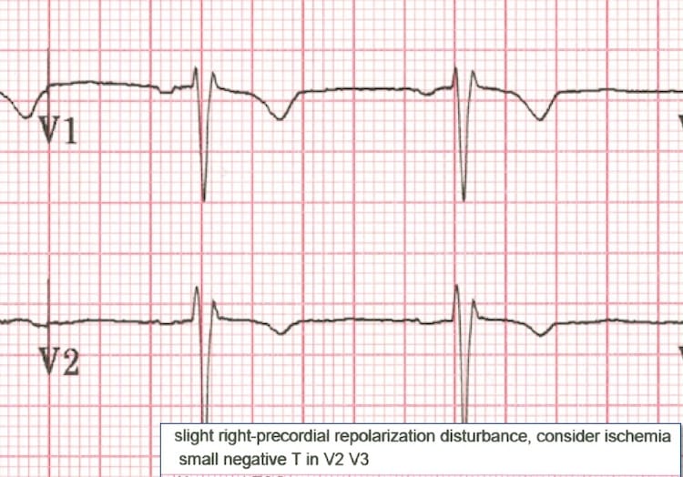
Detail from figure 1. The ECG computer suggested that the clinician “consider ischemia” given the ST/T pattern in V1-V3. Note the fully negative P in V1
IRBBB Example 2

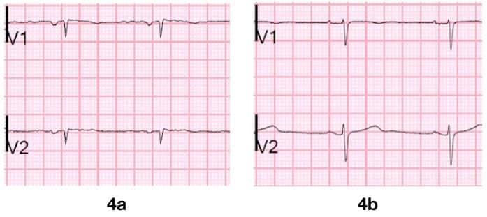
Young woman presents with atypical chest pain. Negative D-dimer, but clinician noted the IRBBB in first ECG (figure 3a), raising suspicion for a PE, and a CTA was ordered. However, V1 and V2 had been placed in the 2nd intercostal space.
When the ECG was repeated with V1 and V2 in 4th intercostal space (figure 3b) the IRBBB pattern resolved. Note that the P wave in V2 is fully positive when leads are correctly located.
Old “Septal MI”
Seemingly new Q waves can be generated with high placement of V1 and V2. If there is supporting clinical context, an old septal MI can be considered, and confirmatory labs and imaging obtained. Otherwise, the ECG should be scrutinized for the signs of misplacement and repeated.
(Dr Smith ECG blog 2018)
False STEMI
In some cases, the rSr’ or qR pattern may combine with a mild degree of benign anterior ST segment elevation (aka “male pattern”). This produces a “saddle-shaped” ST segment that the computer may mistake for acute ischemia.
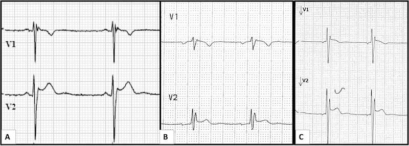
Figure 5: Three examples of False STEMI:
- (A) 23 y.o. man with atypical CP, negative troponin and D-dimer. The computer produced an *** Acute MI*** alert.
- (B) 35 y.o. man, asymptomatic at primary care doctor for an annual evaluation, and again the computer produced an *** Acute MI*** alert.
- (C) 20 y.o. man sent from an employment physical, computer read “consider ischemia” based on V1-V2.
In all three cases, the ECG patterns and computer interpretations resolved with proper lead placement of V1 and V2.
T wave inversion
T wave inversion may be normal in V1 and even V2. However, in patients with symptoms that suggest a cardiopulmonary cause, an inverted T wave must be presumed to be pathologic. Upwards misplacement of V2 can generate false T wave inversion, however, as illustrated in figure 2.
Brugada – Type 2 (Not Type 1)
V1 and V2 may be placed in the 3rd or even 2nd intercostal spaces in order to elicit a type 1 Brugada pattern, and is considered diagnostic.
By contrast, a type 2 Brugada pattern may often be found with these “high leads” are applied to healthy people, especially in fit young males. Finding type 2 Brugada in this context is not uncommon, and by itself carries no diagnostic or prognostic significance.
A number of the examples above show a pattern that could be mistaken for type 2 Brugada.
References
- Walsh B. Misplacing V1 and V2 can have clinical consequences. Am J Emerg Med. 2018 May;36(5):865-870
- Smith S. Chest Pain and Q-waves in V1 and V2. Is there previous septal MI? 2018
- Ilg KJ, Lehmann MH. Importance of Recognizing Pseudo-septal Infarction due to Electrocardiographic Lead Misplacement. Am J Med. 2012 Jan;125(1):23-7.
- Smith S. Saddleback ST Elevation. Is it STEMI? Is it type II Brugada? 2018
- Smith S. Chest pain and T-wave inversion in lead V2. 2018
LITFL Further Reading
- ECG Library Basics – Waves, Intervals, Segments and Clinical Interpretation
- ECG A to Z by diagnosis – ECG interpretation in clinical context
- ECG Exigency and Cardiovascular Curveball – ECG Clinical Cases
- 100 ECG Quiz – Self-assessment tool for examination practice
- ECG Reference SITES and BOOKS – the best of the rest
ECG LIBRARY
Emergency Medicine Physician at Bridgeport Hospital. Devoted student of emergency electrocardiography and echocardiography. Plus all the other stuff | @BrooksWalsh | LinkedIn |
[…] EKG/felplacering: bra exempel på att för högt placerad V2 kan ge bild som Brugada typ 2 med sadelformad ST-höjning. Se tidigare om detta här […]