
![]()
Pacemaker Rhythms – Normal Patterns
Pacemaker Components
1. Pulse generator
- Power source
- Battery
- Control circuitry
- Transmitter / Receiver
- Reed Switch (Magnet activated switch)
2. Lead(s)
- Single or multiple
- Unipolar or bipolar
Pacemaker Classification
- Pacemakers are classified by the nature of their pacing mode.
- Classification follows pacemaker code developed by the North American Society of Pacing and Electrophysiology (NASPE) and the British Pacing and Electrophysiology Group (BPEG).
- The NASPE/BPEG Generic (NBG) Pacemaker Code was last revised in 2002, although many textbooks still use the previous version from 1987.
- The code is expressed as a series of up to five letters.
NBG Pacemaker Code (2002)
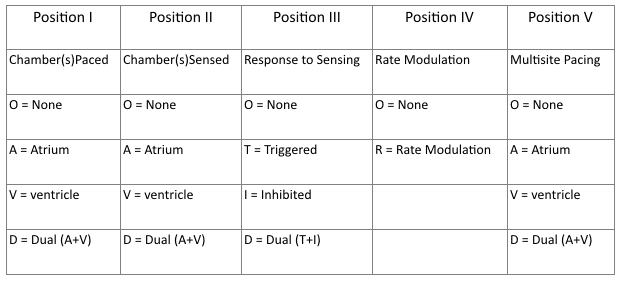
- Position I: Chambers Paced
- Refers to chambers paced.
- Position II: Chambers Sensed
- Refers to the location where the pacemaker senses native cardiac electrical activity.
- Position III: Response to Sensing
- Refers to pacemakers response to sensed native cardiac activity.
- T = Sensed activity results in triggering of paced activity
- I = Sensed activity results in inhibition of pacing activity
- Position IV: Rate Modulation
- Indicates ability for rate modulation designed to altered heart appropriately to meet physiological needs e.g. physical activity. Sensors may measure and respond to variables including vibration, respiration, or acid-base status.
- Position V: Multisite Pacing
- Allows indication of multiple stimulation sites within one anatomical area e.g. more than one pacing site within the atria or biatrial pacing
View the 1987 NBG Pacemaker Code
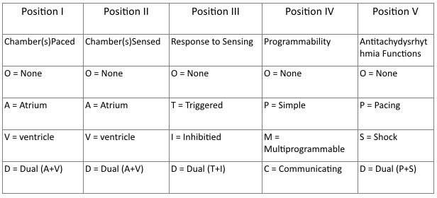
- Positions I – III
- Same as 2002 guidelines.
- Position IV: Programmability / Rate Modulation
- Reflects the programming options available for pacemaker set-up or presence of rate modulation ability.
- Position V:
- Refers to presences of anti-tachydysrhythmia functions. Superseded by the NASPE/BPEG Defibrillator Code.
Common Pacing Modes
AAI – Atrial pacing and sensing
- If native atrial activity sensed then pacing is inhibited.
- If no native activity sensed for pre-determined time then atrial pacing initiated.
- Used in sinus node dysfunction with intact AV conduction.
- Also termed atrial demand mode.
VVI – Ventricle pacing and sensing
- Similar to AAI mode but involving ventricles instead of the atrium.
- Used in patients with chronic atrial impairment e.g. atrial fibrillation or flutter.
DDD – pacing and sensing the atria and ventricles
- Commonest pacing mode.
- Atrial pacing occurs if no native atrial activity for set time.
- Ventricular pacing occurs if no native ventricle activity for set time following atrial activity.
- Atrial channel function is suspend during a fixed periods following atrial and ventricular activity to prevent sensing ventricular activity or retrograde p waves as native atrial activity.
Magnet mode
- Applying a magnet to a pacemaker will initiate the magnet mode.
- This mode varies with pacemaker set-up and manufacturer.
- Usually initiates an asynchronous pacing mode – AOO, VOO, or DOO.
- Asynchronous modes deliver constant rate paced stimuli regardless of native rate of rhythm.
- In asynchronous ventricle pacing there is a risk of pacemaker-induced ventricular tachycardia.
- Note this differs from magnet application to an Implantable Cardioversion Defibrillator (ICD) which results in defibrillator deactivation.
Criteria for Pacemaker Insertion
- The 2002 American College of Cardiology, American Heart Association and North American Society for Pacing and Electrophysiology guidelines for implantation of cardiac pacemakers.
- ACC/AHA/HRS 2008 Guidelines for Device-Based Therapy of Cardiac Rhythm Abnormalities
Paced ECG – Electrocardiographic Features
The appearance of the ECG in a paced patient is dependent on the pacing mode used, placement of pacing leads, device pacing thresholds, and the presence of native electrical activity. Features of the paced ECG are: Pacing spikes
- Vertical spikes of short duration, usually 2 ms.
- May be difficult to see in all leads.
- Amplitude depends on position and type of lead.
- Bipolar leads result in a much smaller pacing spike than unipolar leads.
- Epicardially placed leads result in smaller pacing spikes than endocardially placed leads.
Atrial Pacing
- Pacing spike precedes the p wave.
- Morphology of p wave dependent of lead placement but may appear normal.
Ventricular Pacing
- Pacing spike precedes the QRS complex.
- Right ventricle pacing lead placement results in a QRS morphology similar to LBBB.
- Left epicardial pacing lead placement results in a QRS morphology similar to RBBB.
- ST segments and T waves should be discordant with the QRS complex i.e. the major terminal portion of the QRS complex is located on the opposite side of the baseline from the ST segment and T wave.
Dual Chamber Pacing
- Dependent on areas begin paced.
- May exhibit features of atrial pacing, ventricular pacing or both.
- Pacing spikes may precede only p wave, only QRS complex, or both.
The absence of paced complexes does not always mean pacemaker failure as it may reflect satisfactory native conduction.ECG Features

ECG Examples
Dual Chamber Pacing
Example 1
A-V sequential pacing:
- Atrial and ventricular pacing spikes are visible before each QRS complex.
- There is 100% atrial capture — small P waves are seen following each atrial pacing spike.
- There is 100% ventricular capture — a QRS complex follows each ventricular pacing spike.
- QRS complexes are broad with a LBBB morphology, indicating the presence of a ventricular pacing electrode in the right ventricle.
Example 2
- A-V sequential pacing — atrial and ventricular pacing spikes precede each QRS complex with 100% capture.
Example 3
- Another example of A-V sequential pacing.
Ventricular Pacing
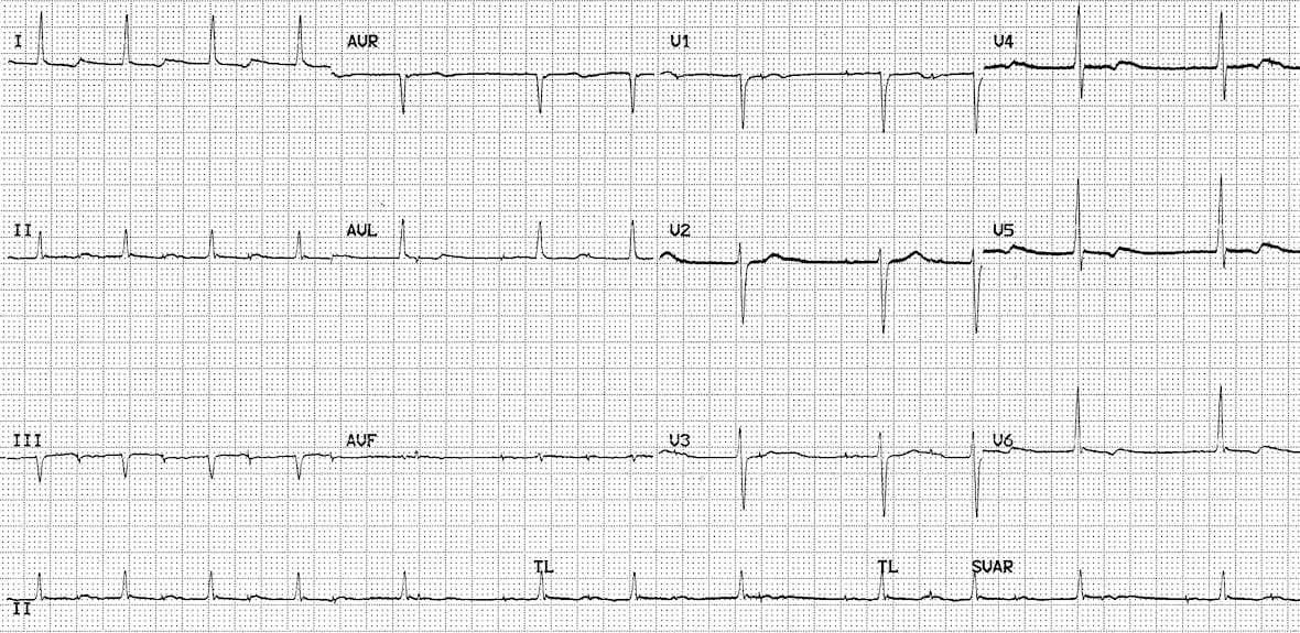
Example 4
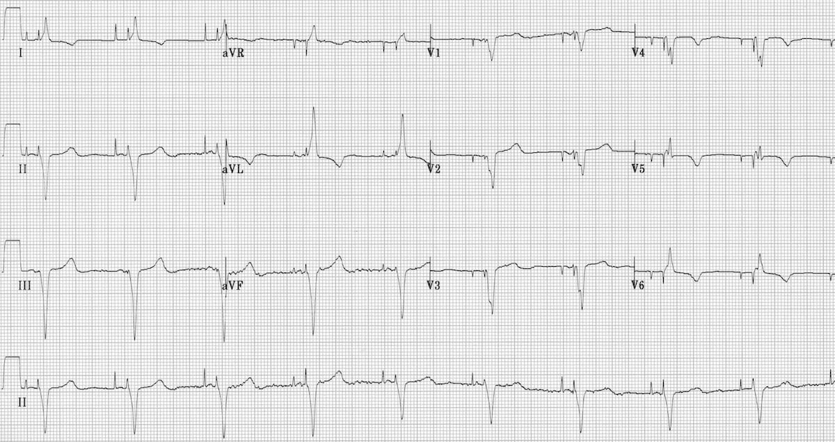
Ventricular paced rhythm:
- Ventricular pacing spikes precede each QRS complex (except perhaps complex #2 — although the QRS morphology in this complex is identical to the rest of the ECG, suggesting that this beat is also paced)
- No atrial pacing spikes are seen.
- The underlying native rhythm is probably coarse atrial fibrillation — there are several possible P waves visible in V1 but otherwise the atrial activity is chaotic.
Example 5
Ventricular paced rhythm:
- Ventricular pacing spikes precede most of the QRS complexes.
- The 6th and 7th beats are narrower, with a different morphology — these are non-paced (“capture”) beats, probably supraventricular in origin.
- There is a pacing spike superimposed on beat #6, but this does not appear to alter its morphology — i.e. no evidence of a fusion complex.

Example 6
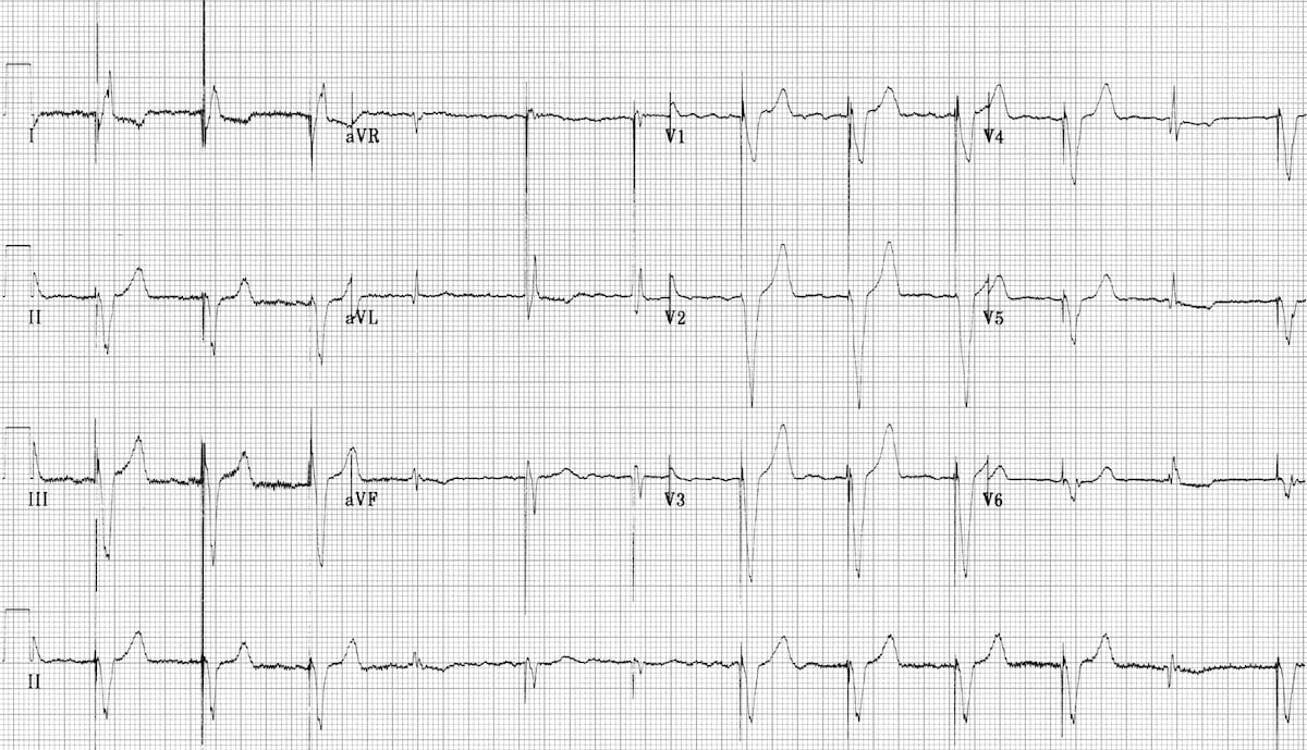
Ventricular paced rhythm:
- Ventricular pacing spikes precede the QRS complexes, most of which exhibit LBBB morphology consistent with a RV pacing electrode.
- The 5th, 6th and 11th complexes are narrower with a different morphology — these are fusion beats produced when the ventricle is simultaneously activated by both paced and supraventricular (native) impulses. You can see how the pacing spike is shortened and the QRS duration narrowed by the co-incident native impulse.
- The 4th complex is probably a supraventricular capture beat, although there may still be some hybridisation with a pacing spike.
Atrial Pacing
Atrially paced patients often have evidence of 1st degree AV block or Wenckebach conduction on their paced ECG that is not apparent on their baseline tracing.
This is because the sort of patients that require atrial pacing (e.g. post-op cardiac surgery) commonly have some degree of AV node dysfunction (e.g. due to age-related AV-nodal degeneration / their underlying cardiac condition / post-operative ischaemia / AV-nodal blocking drugs).
When these patients are paced at a faster rate than their AV node can handle, the AV node becomes “fatigued” resulting in 1st degree AV block or Wenckebach phenomenon on the paced ECG. This abnormality is not clinically important provided that the patient’s cardiac output is not compromised.
Example 7
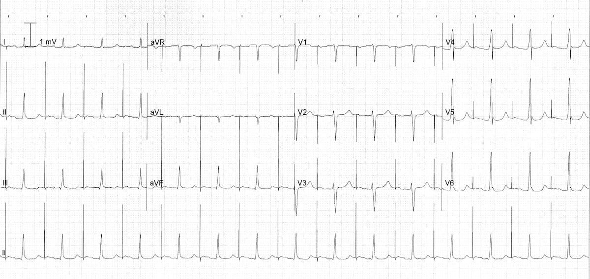
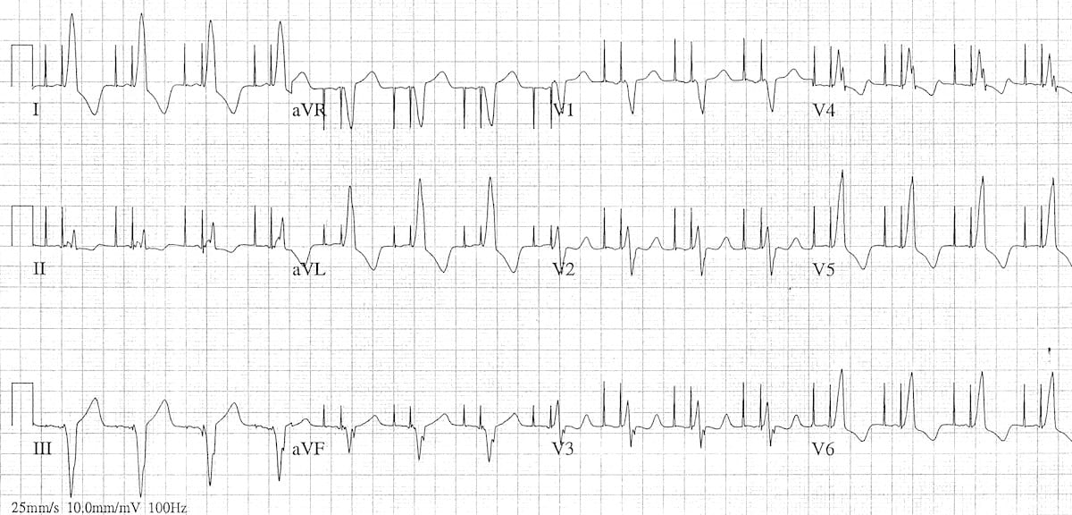
Atrial paced rhythm with 1st degree AV block:
- There are regular pacing spikes at 90 bpm.
- Each pacing spike is followed by a P wave, indicating 100% atrial capture.
- P waves are conducted to the ventricles with a prolonged PR interval (280 ms).
Example 8
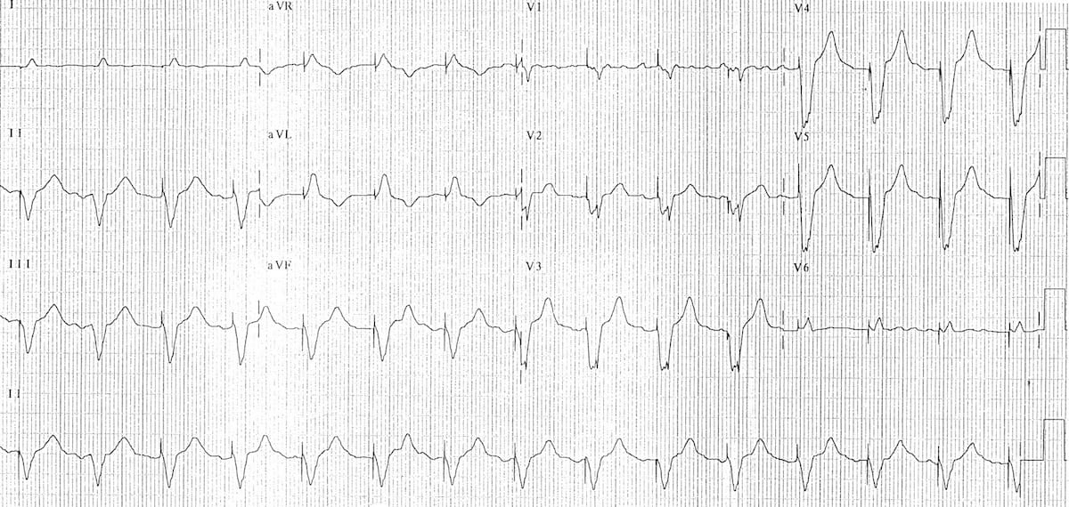
Atrial paced rhythm with Wenckebach conduction:
- There are regular atrial pacing spikes at 90 bpm; each one is followed by a small P wave indicating 100% atrial capture.
- However, not every P wave results in a QRS complex — the PR interval progressively lengthens, culminating in failure of AV conduction (“dropped QRS complexes”).
- There is a co-existent 2nd degree AV block with Mobitz I conduction (Wenckebach phenomenon).
- The Mobitz I is due to the patient being paced at a rate faster than his AV node can handle — at his own intrinsic rate of 50-60 bpm he had only a 1st degree AV block.
To find out the story behind this ECG, check out ECG Exigency 011.
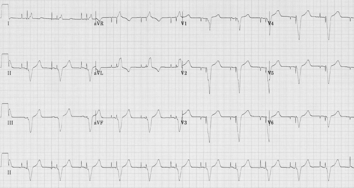
Pacemaker Puzzler
Can you work out what is going on in this ECG?
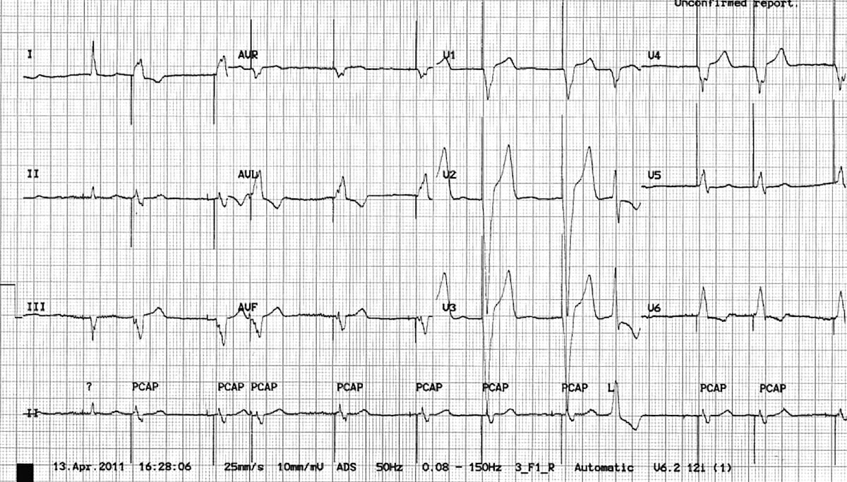
Answer and interpretation
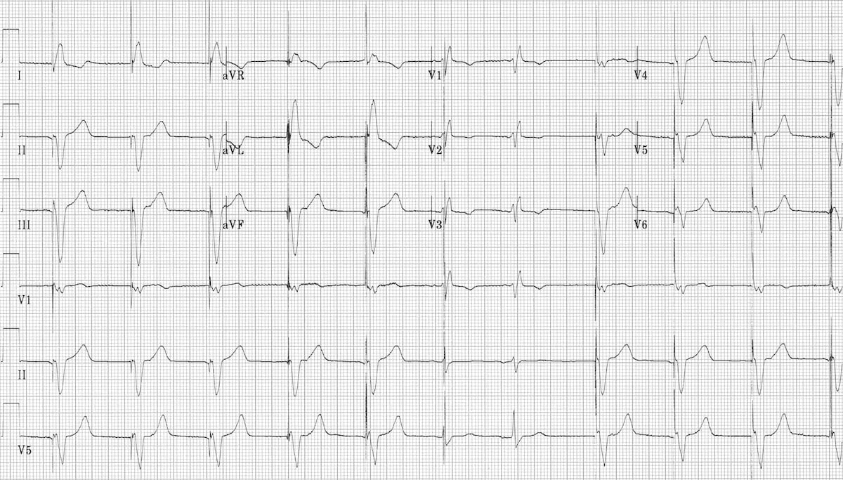
- There is an irregularly irregular rhythm with multiple atrial and ventricular pacing spikes.
- The majority of the QRS complexes are broad (120ms) and preceded by ventricular pacing spikes.
- The LBBB morphology is consistent with a ventricular pacing electrode located in the right ventricle.
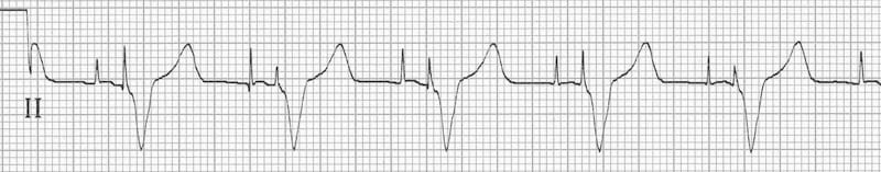
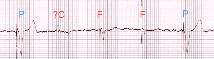
The varying relationship between the atrial and ventricular pacing spikes is best understood by examining the lead II rhythm strip (below):
- Beat 1 is narrow — this appears to be a native ventricular complex triggered by an atrial pacing spike. This indicates that AV conduction is intact to some degree (i.e. 3rd degree AV block cannot be present).
- Beat 9 is broad with a completely different morphology and axis to the rest of the strip — this is a ventricular ectopic beat.
- Beats 3, 6, 8, 10 and 12 are preceded by both atrial and ventricular pacing spikes — sequential A-V pacing.
- Beats 2, 4, 5, 7 and 11 are preceded by ventricular pacing spikes only. The absence of atrial pacing spikes suggests that the pacemaker is responding to native supraventriclar impulses.
- Given the absence of discernible P waves and the very irregular rhythm, it is likely that the underlying native rhythm is atrial fibrillation.
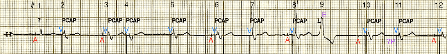
Conclusion
- Atrial fibrillation with DDD pacing and occasional ventricular ectopics.
Related Topics
- Pacemaker essentials: Medmastery
- Pacemaker malfunction
- Left bundle branch block
- Right bundle branch block
- Sgarbossa Criteria
References
- Bernstein AD, Camm AJ, Fletcher RD, Gold RD, Rickards AF, Smyth NP, Spielman SR, Sutton R. The NASPE/BPEG generic pacemaker code for antibradyarrhythmia and adaptive-rate pacing and antitachyarrhythmia devices. Pacing Clin Electrophysiol. 1987 Jul;10(4 Pt 1):794-9.
- Bernstein AD, Daubert JC, Fletcher RD, Hayes DL, Lüderitz B, Reynolds DW, Schoenfeld MH, Sutton R. The revised NASPE/BPEG generic code for antibradycardia, adaptive-rate, and multisite pacing. North American Society of Pacing and Electrophysiology/British Pacing and Electrophysiology Group. Pacing Clin Electrophysiol. 2002 Feb;25(2):260-4
- Gregoratos G et al. ACC/AHA/NASPE 2002 guideline update for implantation of cardiac pacemakers and antiarrhythmia devices: summary article: a report of the American College of Cardiology/American Heart Association Task Force on Practice Guidelines (ACC/AHA/NASPE Committee to Update the 1998 Pacemaker Guidelines). Circulation. 2002 Oct 15;106(16):2145-61
Advanced Reading
Online
- Wiesbauer F, Kühn P. ECG Mastery: Yellow Belt online course. Understand ECG basics. Medmastery
- Wiesbauer F, Kühn P. ECG Mastery: Blue Belt online course: Become an ECG expert. Medmastery
- Kühn P, Houghton A. ECG Mastery: Black Belt Workshop. Advanced ECG interpretation. Medmastery
- Rawshani A. Clinical ECG Interpretation ECG Waves
- Smith SW. Dr Smith’s ECG blog.
- Wiesbauer F. Little Black Book of ECG Secrets. Medmastery PDF
Textbooks
- Zimmerman FH. ECG Core Curriculum. 2023
- Mattu A, Berberian J, Brady WJ. Emergency ECGs: Case-Based Review and Interpretations, 2022
- Straus DG, Schocken DD. Marriott’s Practical Electrocardiography 13e, 2021
- Brady WJ, Lipinski MJ et al. Electrocardiogram in Clinical Medicine. 1e, 2020
- Mattu A, Tabas JA, Brady WJ. Electrocardiography in Emergency, Acute, and Critical Care. 2e, 2019
- Hampton J, Adlam D. The ECG Made Practical 7e, 2019
- Kühn P, Lang C, Wiesbauer F. ECG Mastery: The Simplest Way to Learn the ECG. 2015
- Grauer K. ECG Pocket Brain (Expanded) 6e, 2014
- Surawicz B, Knilans T. Chou’s Electrocardiography in Clinical Practice: Adult and Pediatric 6e, 2008
- Chan TC. ECG in Emergency Medicine and Acute Care 1e, 2004
LITFL Further Reading
- ECG Library Basics – Waves, Intervals, Segments and Clinical Interpretation
- ECG A to Z by diagnosis – ECG interpretation in clinical context
- ECG Exigency and Cardiovascular Curveball – ECG Clinical Cases
- 100 ECG Quiz – Self-assessment tool for examination practice
- ECG Reference SITES and BOOKS – the best of the rest
ECG LIBRARY
Emergency Physician in Prehospital and Retrieval Medicine in Sydney, Australia. He has a passion for ECG interpretation and medical education | ECG Library |

MBBS DDU (Emergency) CCPU. Adult/Paediatric Emergency Medicine Advanced Trainee in Melbourne, Australia. Special interests in diagnostic and procedural ultrasound, medical education, and ECG interpretation. Co-creator of the LITFL ECG Library. Twitter: @rob_buttner
[…] Review on pacemaker modes at: https://litfl.com/pacemaker-rhythms-normal-patterns/ […]